R.N.C. Industries, Inc.
Computer Controlled Bandsaw
R.N.C. Industries, Inc. makes insulation inserts for cardboard boxes. The insulation inserts are made of ROCKWOOL wrapped in plastic. In order to make the inserts for custom size boxes, normally the company has workers cut the ROCKWOOL into rectangles on bandsaws. This requires the workers to interpret various cut sheets and manually measure out the cuts. This method leads to a large reliance on the worker and a potential for inconsistency. The computer controlled bandsaw solves both of these problems and is a very repeatable, elegant solution.
The computer controlled bandsaw (CCB) works with two axes of motion: the first is the cutting motion and the second is the indexing motion. The cutting motion is created by sliding an entire table back and forth on rails on one side of the blade. Bundles of the ROCKWOOL are placed on this sliding table and pushed up against the back fence. The table then moves forward through the bandsaw blade to complete a cut. The length of that cut is determined by the indexing motion. This motion is created by a mobile fence built onto the sliding table. The indexing fence moves the bundle of ROCKWOOL a specified distance, and then the sliding table moves forward through the bandsaw blade generating the cut. A video of the final machine can be seen below:
The CCB is driven by a Raspberry Pi4 controlling an Arduino Mega 2560. The Raspberry Pi controls a touch screen where the operator of the machine selects an excel file containing information about the cut sheet. Once the excel sheet has been uploaded, the Raspberry Pi sends a letter code to the Arduino. Each letter in the code corresponds to a specific cut length. The order of the letters tells the Arduino the order of cuts that the CCB needs to perform. The Arduino converts the cut distances into pulses and sends the pulses to two NEMA 34 closed loop stepper motors: one to index the mobile fence and the other to move the sliding table. To control the CCB, all the operator needs to do is press a button on the control panel. The Arduino updates an LCD screen on the control panel with the previous cut and next cut every time the button is pressed informing the operator about exactly what the CCB is doing at all times. The control panel also includes a repeater switch which enables the operator to continue running cycles of the uploaded cut sheet until the repeater is switched off. The final switch on the control panel is a size switch which changes the travel distance of the sliding table allowing the CCB the flexibility to cut 36 X 48 inch bundles and 48 X 72 inch bundles of ROCKWOOL. The face plate of the control panel was 3D printed in-house to accommodate the custom layout needed.
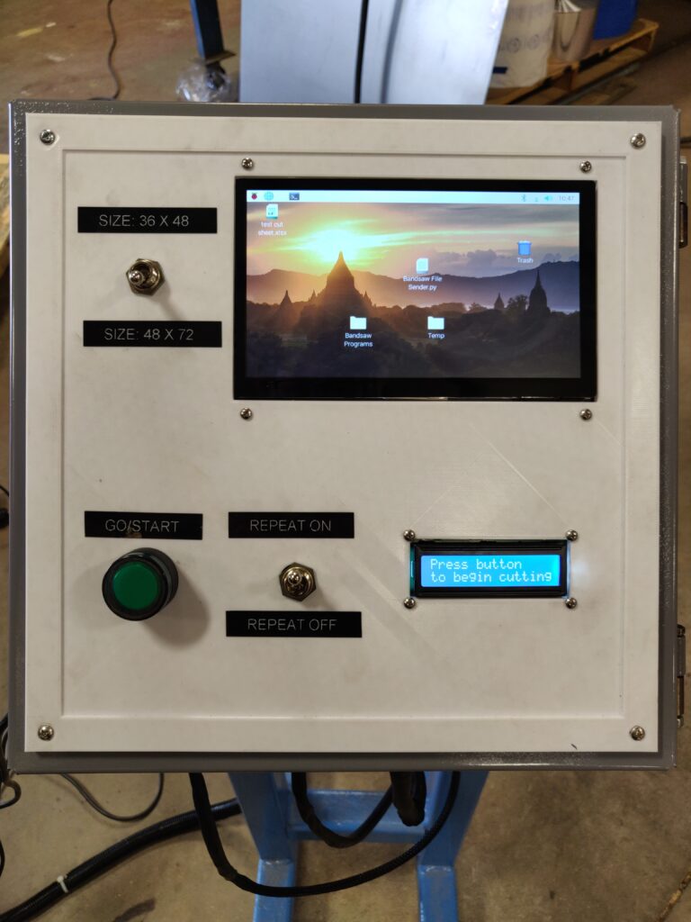


The wiring for the CCB is all custom and completed in-house at R.N.C. The signal wires for the LCD screen and the button and switches needed bespoke cables running between the power box to the control panel. The Raspberry Pi and Arduino communicate through a serial print cable. Two power supplies are needed. One 48 volt to power the two motors and their respective controllers, and one combined 12 volt / 5 volt power supply that give 12 volts to the Arduino and 5 volts to the Raspberry Pi and touch screen.
The entire CCB was designed from scratch. First, the CCB was designed entirely on Solidworks. This made making a parts list and drawings for the fabrication of parts a much more streamlined process. As the Solidworks model was approaching completion, we finished up the initial coding for the machine. The code came in two parts: the Raspberry Pi runs on python and the Arduino runs on C++. The python code involved mainly converting the excel file data into a form that could be sent to the Arduino through the serial communication cable as well as generating the interface on the touch screen for uploading the excel files. The C++ code is where the bulk of the CCB control occurs. The Arduino code receives the letter code from the Raspberry Pi and converts it into pulses to control the closed loop stepper motors. The C++ code also updates the LCD screen throughout the cutting cycle and uses the button and switches to change the actions of the CCB accordingly. There are 4 different cases for how the bundle of ROCKWOOL needs to be cut, and the Arduino code changes the motions of the mobile fence and sliding table to match each case. The 4 cases include a no scrap case, a 48 inch side scrap case, a 36 inch side scrap case, and a double scrap case. Of course, when cutting the 48 X 72 inch bundles the code adjusts the scrap sizes accordingly. To ensure that the scrap cases do not confuse the operator, the LCD screen updates to tell the operator when the CCB is cutting scrap. A video of the Solidworks assembly is shown below:
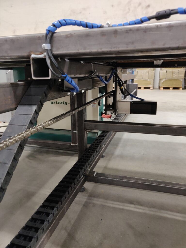
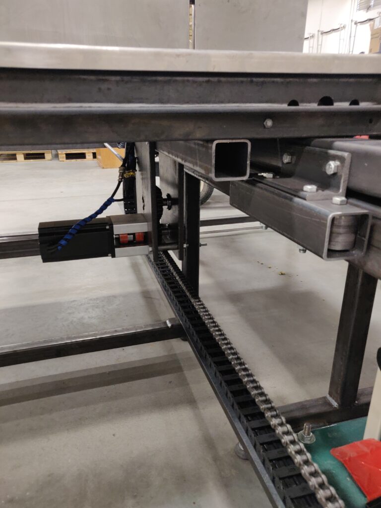
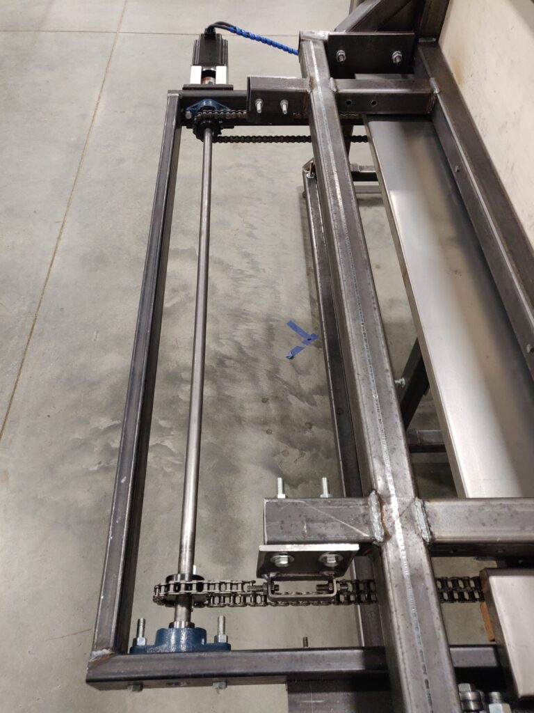
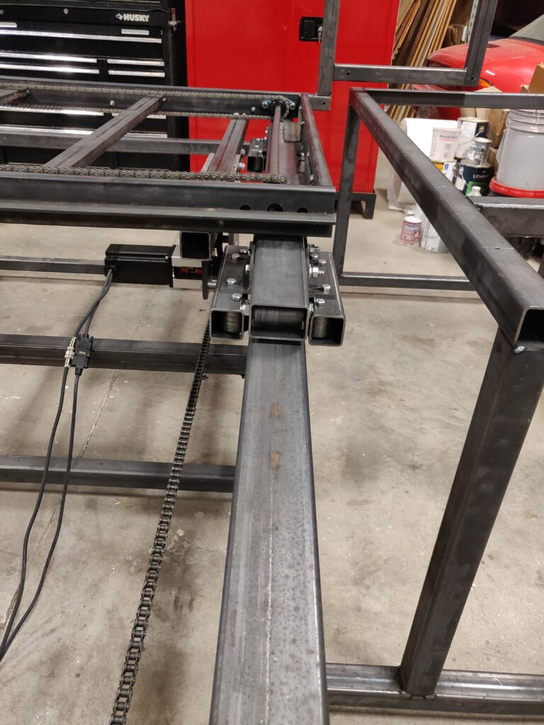
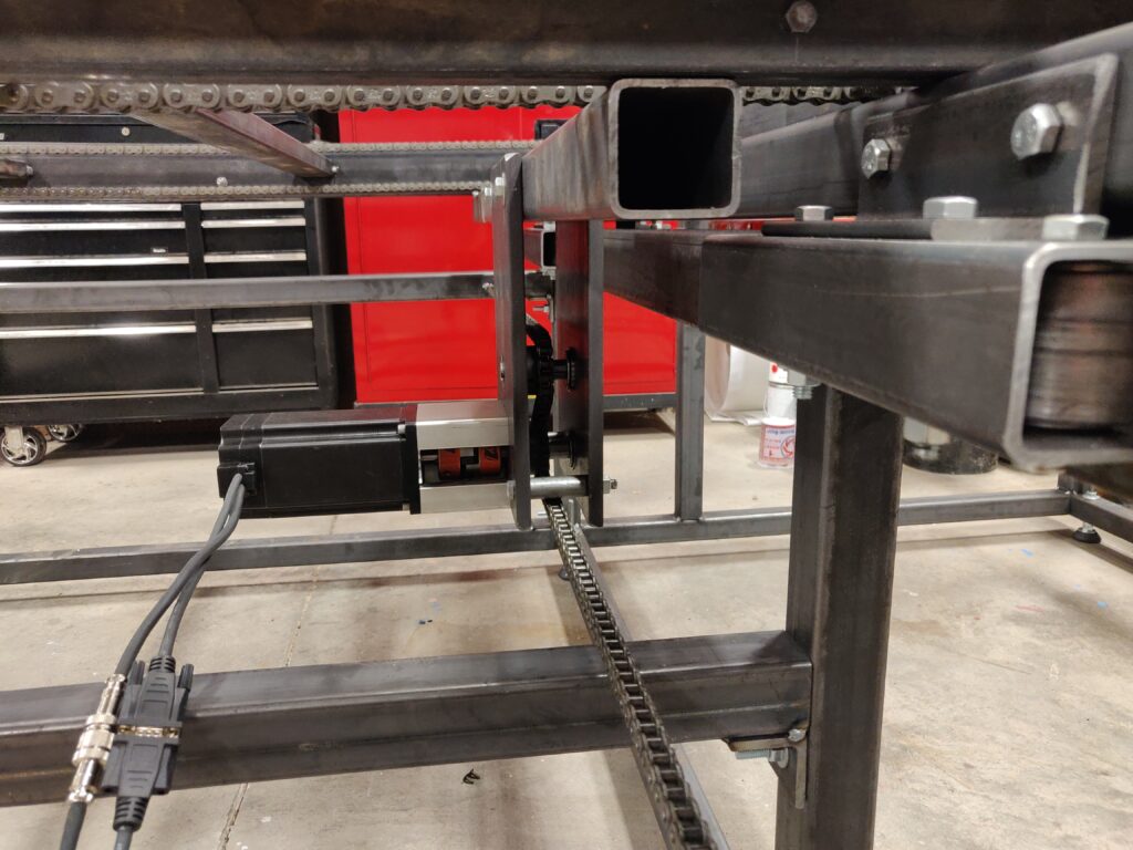
After the completion of the code and Solidworks, the CCB was fabricated completely in-house. We cut 2 X 2 steel tubing and various metal plates according to the drawings from the Solidworks and manufactured every part of the machine. The table slides on steel rollers made in-house and is driven by a chain system similar to a rack and pinion. The chain itself is always stationary while the closed loop stepper motor is connected directly to a sprocket with a love joy and drives the table back and forth along the chain. The mobile fence is connected to a chain and axle system. Two axles, one at either end of the sliding table, are connected with two chains on sprockets at the ends of the axles. The fence is driven using a closed loop stepper motor connected with a love joy to the rear axle.
Bag Machine
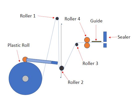
R.N.C. Industries had been working the bag machine for over a year before the summer of 2021. A majority of the machine was built prior to my internship although the machine did not work at all. The purpose of the bag machine is to make the plastic bags used to encase the ROCKWOOL insulation panels. The machine works using a roll of already folded plastic. A stepper motor driven roller lays on top of the plastic roll feeding it through a series of idle rollers, dancer roller (roller 2), and up to two more stepper motor driven feeder rollers (roller 4) that feed the plastic into the head of the machine. The head of the machine is what cuts and seals the plastic. Powered by pneumatics, the head contains two heat bars that, when triggered, fall and make contact with the plastic. The heat bars make two seals and a blade, also power with pneumatics, comes up from underneath cutting between the two heat seals. This enables the head of the machine to make the seal at both the left and right side of the bag as well as cutting the bags apart. Only one side of the bag remains open as the fold in the plastic creates the third seal. The bags are then filled with ROCKWOOL insulation panels and then sealed on the fourth side to make the insulation inserts. A diagram of the system can be seen below:
The problem with the bag machine involved the coordination between the plastic roll feeder, dancer (roller 2), and the head feeder rollers (roller 4). To generate the correct length of bag, the head feeder rollers only move for a certain amount of time while the plastic roll feeder is continuously engaged. The dancer roller moves up and down on a chain and axle system in response to the offset between the head feeder engagement and the plastic roll feeders continuous engagement. The dancer’s primary purpose is to keep tension on the plastic as it is being fed through the system. This increases the accuracy and consistency of the final bag length. The dancer has a limited amount of possible travel distance due to the physical limitations of the machine. The bag machine needed to work accurately for bag lengths ranging from 9 inches to 72 inches. This would not be a problem if the dancer is able to travel 72 inches, however the dancer’s travel is limited to 36 inches. This made accurately making bags in such a broad length range difficult without having the dancer either bottom or top out.
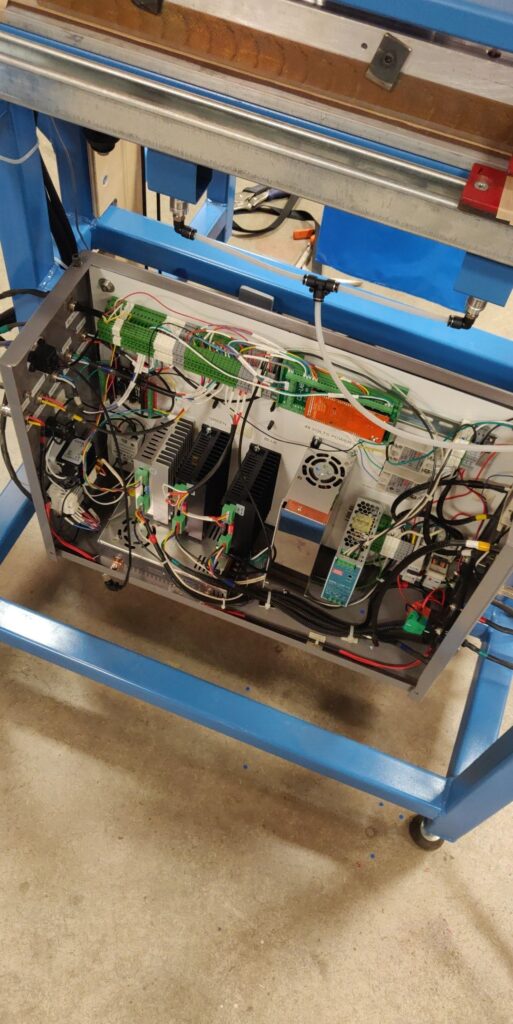
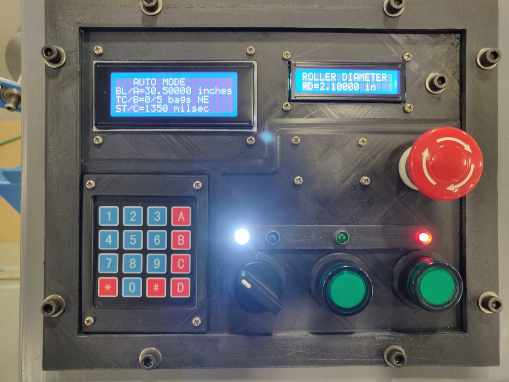
The machine was built originally using two Arduinos. An Arduino Uno controls the stepper motor feeding the plastic roll, and an Arduino Mega 2560 controls the stepper motor for the head feeder rollers, the head movement, and the control panel. The power box and control panel are shown below:
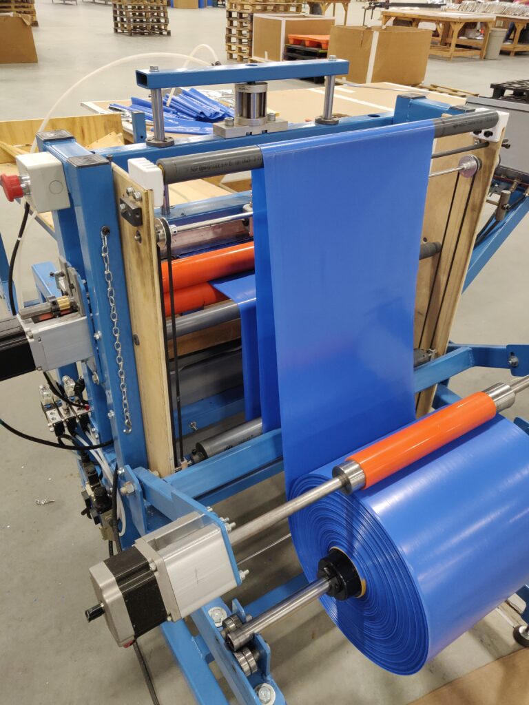
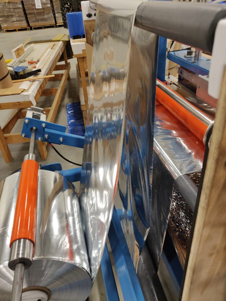
The solution for the dancer problem involves tracking the location of the dancer and enabling communication between the two Arduinos. The Arduino Mega 2560 traces the position of the dancer and sends the location to the Arduino Uno. The Arduino Uno then adjusts the speed of the stepper motor on the plastic roll feeder appropriately making it feed faster if the dancer is about to top out and slower if it is about to bottom out. Initially, we used photoelectric proximity sensors, one near the upper bound and one near the lower bound of travel, to track the location of dancer. Once the dancer comes within a certain distance of the proximity sensor, the Arduino Mega sends a signal to the Arduino Uno telling it to either increase or decrease the speed of the plastic roll feeder. This method worked well initially with the blue plastic that can bee seen above, but the machine also needed to work with Mylar, a very reflective, shiny silver material. The reflective properties of the Mylar caused the photoelectric proximity sensors to fail. A picture of the bag machine with Mylar is shown below:
To solve this new problem, the photoelectric proximity sensors were replaced with an encoder attached one of the axles of the dancer’s chain set up. This allows the Arduino Mega to continuously track the position of the of the dancer. The Arduino Mega sends the continuous position of the dancer to the Arduino Uno which now continuously changes the feed rate of the plastic. As the dancer gets higher, the stepper motor feeding the plastic roll continues to get faster the higher the dancer gets. As it catches up and the dancer falls, the stepper motor slows down proportionally to the location of the dancer. If the dancer falls very low, the stepper motor will slow down almost until it stops. This method keeps the dancer from bottoming or topping out in the very limited physical range it has to move. Below is a video of the bag machine in action: